Hondata Tuning Guide
This guide covers the specifics of tuning a 2017+ Honda Civic Type R from start to finish using a Hondata FlashPro. It was created by Kefi from the FK8 Clinic and is meant for those that are already familiar with EFI tuning and the Hondata interface. There are many videos and courses online about both of those subjects, so many general topics won't be covered in depth here in order to focus on techniques specifically for the FK8. This is not a guide for those who just want to get their Type R tuned on a basemap or a custom tune by someone else. If you do not understand the fundamentals of EFI tuning, you should not attempt to follow this guide blindly. An FK8 ECU is great for someone to learn tuning on, but you must understand electronic fuel injection first. General information regarding tuning a Type R can be found on the main Tuning article.
While much of this guide also applies to KTuner since it is still the Bosch ECU, many of the tables or sensors used are not available or work entirely differently (i.e. KTuner has boost pressure limit tables, not ratio tables). We recommend using Hondata, but it is possible to get similar results on both platforms.
Disclaimer
You are fully responsible when using the information in this guide. This is meant to be purely informational on a platform where there is very little info, and some things may not be correct or even safe. Lots of this information is guesses made after years of experimentation. Many of these techniques are still being refined or even discarded due to the ongoing developments in understanding the FK8 platform. There is no one way to tune a car. While the ECU is considered 'relatively safe' to tune on, you still can push the engine too far and damage or destroy it, especially if you are not doublechecking the torque output with a dynamometer. Just because your torque request is set to a certain 'safe' torque does not mean the ECU won't significantly overshoot the torque you request, and it is quite easy to do so.
Core Concepts
To tune a Civic Type R, you must first become intimately familiar with a few concepts that affect nearly every aspect of the tuning process.
Bosch ECU
The 10th generation Civic Type R does not have a Honda ECU, instead featuring a Bosch MED v17.9.3 which is essentially a one-size-fits-all ECU for OEMs. The techniques for tuning them are significantly different.
Luckily, Hondata has managed to make their FlashPro tuning platform and most of the advanced features like traction control work with the Bosch ECU so existing Hondata tuners do not have to learn an entirely new tuning platform. The only other Honda to feature this ECU was the 2015+ European FK2 Civic Type R. It is also commonly seen in BMWs and VWs, although each Bosch ECU has it's own set of techniques the manufacturer has chosen to use and the 17.9.3 is specific to Honda.
The biggest thing you'll need to get used to is that the ECU does many things on its own, most tables are limits rather than targets, and nearly everything has inertia or PID control. The downside to all this is that the ECU is insanely complex and it's that much harder for Hondata to find the correct tables, parameters, and routines to replace. There are many behaviors we still haven't figured out and may very well never figure out. If you've ever asked 'why doesn't Hondata add X/Y/Z, they had it on other platforms', it's because it's an absolute nightmare to fiddle with even the simplest of things on this ECU. Hondata owns multiple daily driven Type Rs. If it was worth the time, it would be there.
However, the dynamic nature of this one-size-fits-all ECU ends up being beneficial to tuners. All of the calculations are all real-time and not hardcoded into the ECU, so we can modify higher level parameters and the ECU will fill in the blanks and keep most things in check.
Air charge model
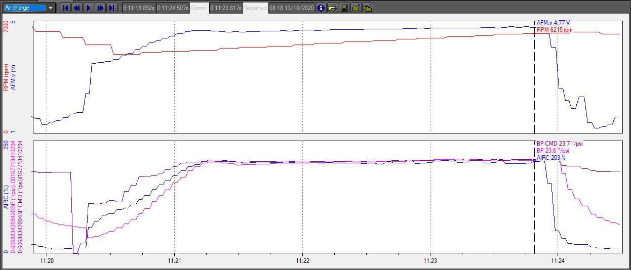
Note that the majority of this section is a guess. At this time no one but Honda has a copy of the Bosch calibration guide that describes the air model in detail. What we know is that the Bosch ECU uses a significantly more accurate load index for targeting fueling, ignition, and cam angles. It calculates how much air is actually inside the cylinder rather than the overall flow through the intake and engine. It is a ratio expressed as a percentage of the physical mass/amount of air in the cylinders at bottom dead center compared to how much the cylinders would hold at the currently measured atmospheric pressure. Anything above 100% and the cylinders are under boost, anything below 100% is vacuum.
The actual mass of air throughout any turbocharged application's intake and cylinders varies wildly, particularly during sudden throttle changes. Things like VTEC can significantly change the amount of air in the cylinder for each stroke despite the overall flow and calculated engine load not instantly changing, and since VTEC crossover generally happens around peak torque it's vital for this measurement to be correct at that immediate time. By having an immediate measurement of the mass of air in the cylinders instead of just what is passing by the MAF sensor or how much pressure the manifold is under, the Civic Type R is able to target a theoretical amount of torque reliably under all environmental and operating conditions with significantly less room for error, regardless of what modifications are installed.
Air charge algorithm
Air charge is very similar to both SAE absolute and relative engine load and uses the same sensors, but the calculations are time-domain rather than instantaneous and are also significantly more complex. The actual formula is not known or standardized like SAE engine load, but we have a guess. The ECU will first track how much air has flowed past the MAF sensor into the charge pipes, determining how much pressure that airflow is maintaining before the throttle plate using the boost pressure sensor. It will also watch the manifold pressure after the throttle plate to determine how much of the air is entering from the charge pipes, leaving out of intake manifold and thus (hopefully) going into the cylinders. Because the ECU is sampling the MAP sensor in high resolution in order to properly measure the pressure drops as the intake valves open, datalogs will usually show it fluctuating under load by 1 to 2 psi.
This tightly controlled calculation is the reason why the all-too-common vent-to-atmosphere blowoff valves (or any other way for the air to escape unmeasured i.e. boost leaks) or 'performance chips' that intercept the sensors can potentially reduce the reliability and safety of the engine, despite everything looking normal mostly in datalogs.
Torque targeting
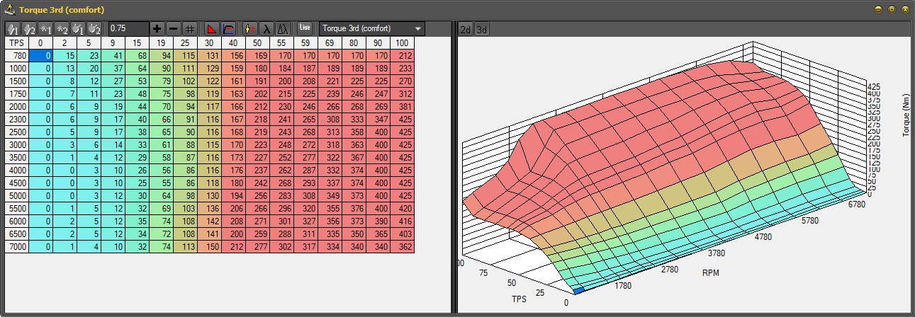
Everything begins with the throttle pedal position and current RPM corresponding to a certain amount of requested torque, with an individual table for each gear and drive mode totaling 18 torque request tables.
The ECU will calculate how much air charge is required to achieve the requested torque, up to the limits defined in various tables. The air charge will determine boost pressure command, and then from that the throttle plate position and wastegate position. You do not directly tune boost pressure on an FK8, but you can effectively tune in the same manner as boost by gear with more consistent power results.
It is critical to know that while these tables will result in the engine outputting approximately the torque you request, it can easily overshoot the requested value. You must use other tables to limit the output. It is very easy to overshoot the torque by even 50lbft of your target torque while spooling.
While other Honda platforms are compared by their targeted PSI, it is more appropriate to compare an FK8's capability and tune by the targeted air charge.
Flashing
The process to flash a Bosch ECU is exactly the same as a Honda ECU, but it takes significantly longer (five to eight minutes) and requires a short period of driving afterwards to properly learn the stoichiometric lambda baseline before the closed loop system comes online. You will need to slowly drive (either on the dyno or road) in various gears for about two minutes until AF is no longer pegged at 14.7. You can idle as well, but the learning process will have more accurate initial results and come online faster by giving it different conditions while it is learning.
This means you're looking at roughly eight to twelve minutes between starting the flash and doing another pull, so plan accordingly for the dyno. There are some tables that can be live tuned to save you flashes and time, but that is covered in another section of this guide and many of the tables you will want to change are not live tunable anyways.
Knock
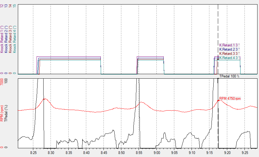
Unlike other Hondas, the Type R does not use a traditional knock control strategy that learns a fuel's octane level over time. Instead, when the knock sensor picks up noise outside of a certain window, ignition retard is gradually applied to the knocking cylinder and will only remain until throttle input is reset. This system has no memory and will consistently allow knock, albeit rapidly eliminating it once detected.
Due to the nature of this knock strategy, the factory knock sensor calibration is also extremely sensitive and will regularly pick up noise and register more false knock than most platforms. However, because the ignition retard is incremental it has very little effect on power from these tiny false knock events and the sensitivity should generally be left alone unless there is a significant amount of noise from a part such as an exhaust.
This is important to know, because it means that improperly tuning ignition or using low quality fuel can result in consistent knock that never goes away and the driver would never know unless they reviewed their logs.
Calibrating knock retard
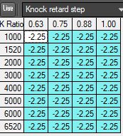
There are two parameters to the knock retard system: step and window. The step is how much ignition retard is applied in each 'step' the knock retard system takes expressed as a negative number of degrees, and is -2.25 degrees from factory. It is recommended to set the step to -3 or more when you are working with uncertain fuel or testing new ignition values, and -0.75 to -1.50 if you are certain the fuel is consistently high quality and no knock normally occurs. This is one place where a conservative tune differs from an aggressive one.
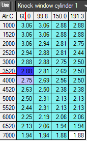
The knock windows can also be increased in order to decrease the sensitivity of the knock retard system, but extreme caution should be exercised in doing so because you will potentially miss real knock. Generally speaking, increasing the values by 10 to 20 percent is sufficient for even the noisiest of FK8s. There is a separate table for each cylinder, allowing fine tuning for difficult cylinders. You should adjust it until you're just barely seeing noise, but still seeing it. If you completely eliminate noise, there's a good chance you won't be picking up knock early enough or at all, making the knock retard strategy significantly less effective.
We recommend putting these changes, especially the step, in the tuning notes so that the customer or anyone helping them diagnose issues knows what to expect when looking at datalogs.
Identifying real knock
Due to the regular presence of noise and false knock, it's important to know what real knock typically looks like on an FK8 and when it can be passed off as noise. Note that 'steps' here refers to the total KR divided by the requested amount of step, not separate increases. For example, 3 steps at -2.25 is -6.75 while with a -0.75 step it's only -2.25, but both indicate the same amount of knock being detected.
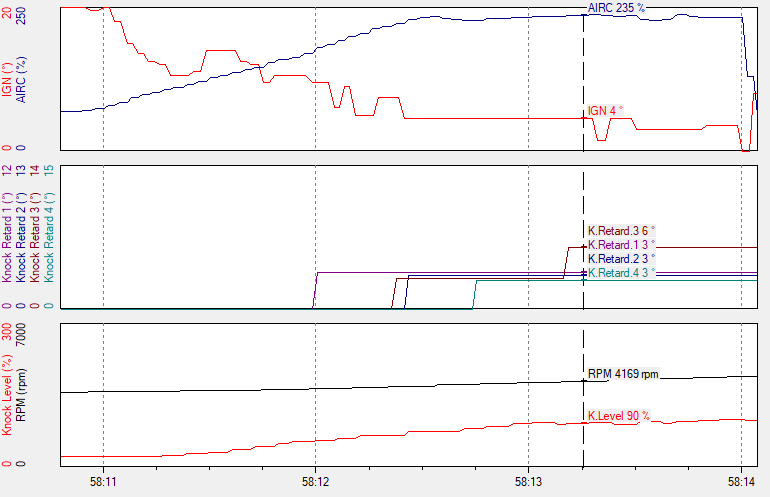
Knock can be most easily identified by any number of steps that gradually increase across three to four cylinders, the so called 'rainbow knock'. Seeing three steps in two cylinders or more than four steps in a single cylinder is also cause for investigation.
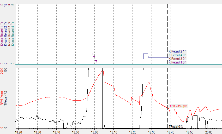
However, seeing lots of little single cylinder one-step spikes across a datalog is not a concern, especially if it occurs right when the throttle is applied and not somewhere along the pull near redline.
Airflow metering
How torque request relates to boost and ignition
As described earlier, the ECU begins the calculations with torque request tables for each gear and drive mode corresponding to pedal input and RPM, totaling 18 maps. Using an internal model of the engine we have no control over, it will approximate the necessary air charge required to produce the requested torque under current atmospheric conditions. Remember that additional air molecules are ultimately what makes more power, with other parameters just making the energy output of the air more efficient or safe. As such, the engine is able to take a theoretical torque request and convert it to the necessary air mass, assuming a perfect burn.
The ECU monitors the torque output of the engine (something we unfortunately cannot datalog yet) and will modulate ignition up to the limits specified in the ignition tables in order to meet the requested torque. This is not calculated ahead of time as there is no mathematical formula for determining the torque output of a given ignition advance like there is for air mass. As such, when you begin advancing ignition past the factory values it is very easy to overshoot your requested torque when the turbo is spooling.
This relationship between ignition and air charge is the single hardest part of tuning a Civic Type R, as it will leave tuners new to the platform wondering why their changes aren't working or why ignition is randomly reduced.
If you are already making the requested torque while not yet reaching the maximum ignition values, adding additional advance in the tables will not result in ignition actually advancing until air charge is further limited (either by you or by being in different environmental conditions) or the torque requests are increased. We refer to this condition as the ignition being 'torque limited'. You should generally not have your ignition be torque limited under normal conditions since it could lead to ignition values that you did not actually test being targeted later on. It is ideal to be as close as possible, though. This balance can also be exploited in order to target more ignition when boost is expected to be intermittently limited by something else like high altitudes or IATs, further separating a good tune from a great one. The factory maps use this technique to an extent. However, this is difficult to do and requires a LOT of hands on experience to get right.
In short, the ECU targets a set amount of air that should theoretically be capable of producing the requested torque and then modulates the ignition advance on the fly in order to actually meet the requested torque.
Limiting boost
The amount of boost that the ECU targets is dynamic, but can be directly limited in a couple of different ways other than simply lowering torque request.
Air charge limits
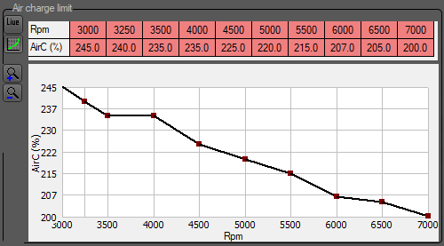
You can set a limit on the amount of air charge the ECU will attempt to target at any given RPM via the air charge limit table. This table is a normally deactivated Bosch feature that is not used in the factory calibration, but is used in all of the basemaps and almost every custom tune. It is still possible and very common to slightly overshoot these limits as it is only limiting the internal target and not actually making corrections on the fly to reduce air charge once the limit has been exceeded.
Turbo ratio limits
Although the ECU calculates target boost pressure on its own from the target air charge, there are turbo ratio limit tables available that will act as a hard ceiling for the boost pressure target. No other parameter in the ECU will override the limits in these tables, so you can use them to reliably limit the compression ratio and turbine speed of the turbocharger, albeit still not directly setting any specific PSIG as you would with other platforms. For the most part, setting these limits is not absolutely required since other tables will limit the turbocharger, but some tuners may elect to use these tables. The Hondata basemaps have these limits purposely set a few PSIG past what you would see under normal conditions, and really only limit the turbo in high altitude or high air temperature scenarios. The factory map relies on these tables since it does not use the air charge limits.
The values are expressed as a ratio of absolute turbo inlet pressure to turbo outlet pressure. It is not absolute bar pressure or gauge pressure. It is also vital to consider that as the volume expands throughout the intake tract, primarily in the intercooler and the intake, there will be pressure drops before the air reaches the boost pressure sensor and ultimately the cylinders. The amount of pressure lost will increase as airflow increases. The ECU will account for this pressure drop automatically and BPCMD will be accordingly lower, keeping the ratios intact. However, this means you will have to keep the pressure drop in mind while calculating your ratios or you will have lower boost than expected. It's better to use these tables as a safety backup rather than a means to tune power output, and that is their original purpose.
Ratios to PSIG
Converting without pressure drops
To convert from a ratio to the maximum relative boost pressure the ECU will attempt to command before taking pressure drops into account, use the following formula, where PA is the current atmospheric pressure in bars:
Boost PSIG = ((Ratio * PA) - PA) * 14.5038
Calculating pressure drops
This is significantly more complex, as there isn't a set number that works for every Type R and there is no easy way to measure it. Larger intercoolers and other aftermarket intake parts can drastically change the amount of pressure that is lost. This equation does not take losses from temperature into account and also simplifies things by not calculating pre and post turbo pressure drops separately. However, if we know how much pressure has been lost at a certain flow rate, we can calculate the pressure loss at any other flow rate as well. Pressure drop will increase as a square of the volumetric flow rate increase, i.e. double the flow is four times the pressure drop and four times the flow is sixteen times the pressure drop.
To figure out approximately how much pressure loss the ECU has calculated so you can use it in your own calculations, you will need to first know:
- The theoretical max BPCMD found from the previous formula
- The actual BPCMD at a certain flow rate at WOT where BPCMD is not held back by air charge limits
Due to the turbo limit tables having an RPM axis, you will also need to know the maximum mass airflow throughout the RPM range to properly calculate the pressure loss at any particular RPM. You can use the X/Y graph to find this, plotting RPM vs MAF at WOT on a datalog.
Live testing turbo limits
It is easy to plot the maximum boost pressure against your torque requests at the current atmospheric conditions. Simply key on the ignition and start datalogging, and the BPCMD will change with pedal input and gear mode even though the engine is off, simply using the lowest RPM cells. You can use Hondata's live tuning functionality to update your air charge and turbo ratio limits on the fly with the pedal down to see how the ECU calculates boost pressure, and switch between comfort/sport/R+ to quickly try different torque request curves which cannot be livetuned.
The numbers you see will be the highest value the ECU will ever target in the current atmospheric conditions. It should almost perfectly match the calculated PSIG from the previous section. In real world driving conditions the ECU will target less pressure because it will be taking pressure loss into account.
